During the First Meeting of Electronic Arts in Florianópolis, we built a Breathalyzer using the Alcohol Gas Sensor MQ-3 and an Arduino Board to use in the last day of the meeting, in which we gave a party. You can see a quick video two posts below. Last days I received many emails asking for the code or how to make one, so I decided to build the sensor again, take pictures/videos and make a tutorial showing how you can make one, so here it is.
Parts Needed:
- Arduino Board
- 10x 5mm LEDs (Green, Yellow and Red)
- 100KΩ Potentiometer (to calibrate the sensor)
- 10x ≈ 220Ω Resistor (anything between 220Ω and 470Ω is OK)
- BreadBoard
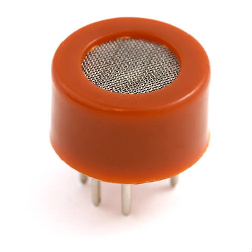
- MQ-3 Sensor from Sparkfun
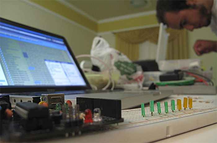
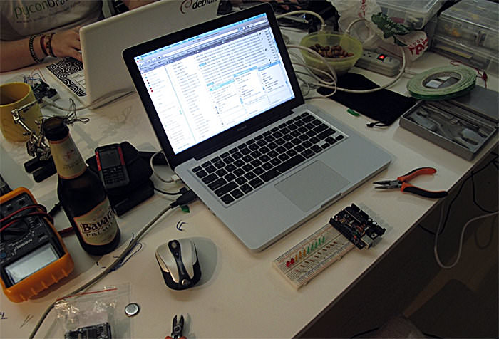
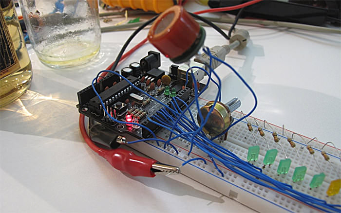
Here are some pictures from the building process:
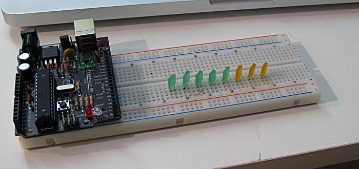
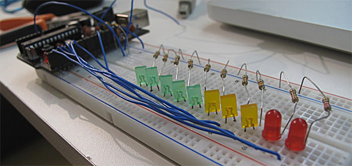
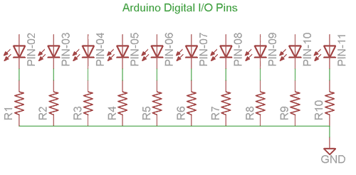
To make the LEDs work, I have connected them in sequence using the Digital Pins 2 till 11 (ten LEDs total). Remember to use a resistor between 220Ω and 470Ω for each LED, like shown on the picture below:
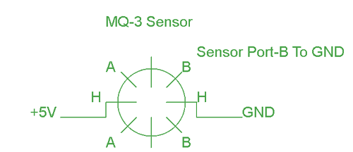
To connect the sensor, you have to connect one of the H pin to +5V Supply (use an external power supply for that, it may be too much current for the arduino) and the other one to Ground.
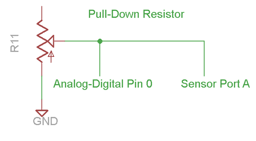
Pin B (any of them) you connect to Ground. And the A pin (also any of them) you connect to the 100KΩ potentiometer as shown on the picture below. In the same pin where you are connecting the pin A, you need to connect a wire to the Analog/Digital Converter in Arduino, that is where you are going to read the Alcohol information.
This is a quick and easy DIY project, but if you have any problem building it, please feel free to post questions!
You can DOWNLOAD the .PDE file HERE.
And now, have a great drinking!!!
Remember, if you gonna drive, don’t drink,
but if you do, call me!!
hilarious! joão, how can u be so hilarious!!
great boys, congrat…
1. does the beer integrate the part list?
2. did you use fritzing to draw your schematics?
kisses
@carol
1. not beer, but Velho Barreiro (stronger 35%, soon I will add video)
2. I used EagleCad. I tried using Fritzing, but I didn’t liked.
🙂
RE Fritzing: I love it. But to grow to love it, I had to get the latest beta version. It is very much improved. The version that is in most Linux repos is old.
If you’re using the Windows version, well, there’s your first problem.
Have you done any work on converting the lvls to Alc/Vol
eg millilitre(alcohol)/Litre(air)
Good job on the excellent writeup.
Great project! I have no need for one but I could test it for you. 🙂
On the datasheet of MQ3 I’ve read that this sensor need a pre-heat time >24hours. Is really needed to preheat the sensor all this time?
I am trying to build a breathalyzer and I am trying to upload the code to my Arduino uno here but I am running into a problem. The code compiles and then when I go to upload it to the Arduino it gives me this error code saying “problem uploading to board. I am sitting here trying to figure this out why I am having this problem. Anyone have similar problems. and if so how did you guys fix it.
Did you try changing the port? Its under tools on the Arduino program. For some reason it does this because it isn’t able to upload through one USB port and you have to change it to another one.
@Gianni time > 24h is a lot!
I’m not sure about that, I didn’t used it to make exact measurements so I can’t tell about it. 🙂
After the “burn-in” part (24h turned on), I’ve found it:
“the heater needs to be on for about 3 minutes (tested with MQ-2) before the readings become stable.”
font: http://www.mouser.com/ds/2/744/Seeed_101020006-786550.pdf
Cool. I love that the Arduino can be used for projects like this.
@Daniel: Yes I know >24 is a lot… I suppose that this time period is to obtain most precise measurements
Did you use a resistor on the sensor?then what is the value of resistor?thnx!
@dan I used a 100KΩ Potentiometer to calibrate 🙂
hey bro you left the one pin of potentiometer open. where to connect it? plz tell me 🙂 thanks
what is the use of pulldown resistor at pin-A of the sensor?should i connect the port A to a resistor?thanx!
@dan http://en.wikipedia.org/wiki/Pull-up_resistor
and yes, you need to connect the resistor 🙂
good job. you can make the schematic of the entire assembly and post it?
can you pls post the schematic and all the connections to the breadboard?thanx in advance..=)
can you explain this line of code:
int ledLevel = map(sensorReading, 500, 1023, 0, ledCount);
and how can we measure the electrical current from the analog input converting to digital output ???
could u post the complete code please? 🙂
thanks a lot 🙂
This will NOT work if wired the way you describe. Sensor pin B needs to be connected to VCC, not GND. Current needs to flow between A and B (direction does not matter). If you connect B to GND, and A to GND (through a resistor) no current flows. I have the MQ-3 and use it for similar circuits. Look at the datasheet. Just to verify, I did wire a circuit just as you describe, and of course there is no voltage at the analog input of the Arduino. Just connect B to VCC and everything will work.
Michael is right. Sensor pin B needs to be connected to power for this to work.
Is it possible to build the breathalyzer using the MQ-3, but not using the arduino?
Sure it is possible! But you will need a way to measure the voltage from the sensor some other way.
Hi, how good is this breathalyzer, for how long it can measure the alcohol in blood, or this is only measure for a short period of time when the alcohol ate in the mouth?
Thanks for this. Very informative, and it helped me build this fireplace breathalyzer for my Christmas party:
http://vimeo.com/17752413
I used the light to indicate when it was taking the reading, not display the result — but the inspiration came from your version.
For people who are asking how to calibrate it or convert values to mg/L blood alchohol levels, see page 2 on this pdf http://nootropicdesign.com/projectlab/downloads/mq-3.pdf
@geoff Congrats!!
@hammy Thanks for the info! 🙂
Very good this project! But, how many doses of “Velho Barreiro” were necessary to test? eheheheheh….
Daniel
DO you have the circuit of this project?
@jaclyn what do you mean by that? If I have the scheme?
Why we need to calibrate the sensor? The pin A of MQ-3 connect to port analog/digital pin 0. The potentiometer 100k one leg connect to gnd and another leg connect to analog/digital pin 0?
How to calibrate the sensor?
i bought a Figaro TGS822 sensor, anyone use it??! there is any way to calibrate it…??!
Do you mean a 10K potentiometer, not 100K. I couldn’t find a 100K potentiometer for Arduino.
what a superb project…………… if even provided with brief circuit
@omee what do you mean by that? The circuit is there, just read the post 😉
I am in a robotics class in highschool and I am trying to do this for a final project I was wondering if i could use any other boards other than the Arduino board?
Is it possible to use a Propellor microcontroller?
Sure you can! Just modify the code
how many leg does mq-3 have? 6 or 4?
MQ-3 have 6pins, but in circut you will need only 4 .. look into the datasheet http://www.sparkfun.com/datasheets/Sensors/MQ-3.pdf
I recently built this breathalyzer to a T. The only problem I have with it is that when its turned on all the LEDS are lite. Why is this? Do I have to edit the code at all? PLEASE HELP!
@Kevin you have to calibrate it with the potentiometer 🙂
Great tutorial guys. This helps loads for my final project.
I just have one question about the wiring in this picture http://img.photobucket.com/albums/v107/tigerbr/MQ-3.gif
Is there any way to tell which side is A and which is B? Or can it work either way?
@Ian you can check that there is a difference between A side and B side just looking! 🙂
What type of arduino board did you use for the proejct could you direct me to the exact model number?
Can u give me a link to ur schematic or circuit diagram about ur project cz i m facing a problem regarding my circuit…
thx in Advance
@Ishan you can make your own schematic looking in the datasheet http://www.sparkfun.com/datasheets/Sensors/MQ-3.pdf
@Alex You can use any arduino board, i used the 2009. http://www.arduino.cc/en/Main/ArduinoBoardDuemilanove
How can we take the output from the ardiuino board to some other application other than the ‘serial monitor’ in the arduino s/w?? we are tryin to develop an electronic nose using artificial neural nw, so we hav to get d o/p in analog form… also the sensor is always showing some values even if we remov it frm ‘alchoholic air’…
do help me
thanx!!
If you still need help with this send me an email I have just completed an electronic nose using the MQ sensor series and an arduino. nickmuir@y7mail.com
Nick
How should the potentiometer be wired? Should it be connected to my A0 analog port??
Tentei reproduzir o projeto usando o mesmo esquema é o Arduino Mega 2650, mas o sensor MQ-3 retorna apenas o valor 0 (zero), mesmo quando há presença de alchool. O que está errado? Como posso identificar o problema?
Sir you could have shown the complete circuit diagram along with procedure
Sir you could have given the circuit diagram along with procedure. Next day after posting this comment could you please show the daigram
Could you show the circuit diagram
I ran across your blog, i believe your web site is awsome, keep writing.
Are you still active in answering questions for this project? Or are you tired of it? Ha
I have what appears to be a common question that I still can’t seem to understand.
I have the whole circuit built. The potentiometer part I still can’t dem to get right. Or I need to know its right so I can rule it out as my current problem.
I am realatitvly new to all this, but I have built my own projects in the past
Let’s please keep it in simpliest terms for everyone.
100k pot has three legs. One SIDE leg goes to ground. The CENTER leg goes to analog input A0. The OTHER SIDE leg goes to MQ-3 pin A.
Can you please confirm or correct. Thank you very much!
Hey guys this is an awesome project and I am interested in doing the same for a biomed electronics project. Anyway you could e-mail me a parts list and any pointers? Thanks alot!
do i have to use the mq-3 or can i use everey gas sensor i want?
great work btw 😉
Hi Daniel,
did you connect all 6 pins from sensor to the Arduino or only 4 of them ? What value did you used for load resistence ?
The detection concentration scope of your sensor was 0.05 to 10 mg/L of alcohol or 0.04 to 4 mg/L of alcohol ? I ask you this because I have found on Internet 2 differnts datasheets…
Thanks
Or did you connected like in the link below???
http://wiring.org.co/learning/basics/airqualitymq135.html
Yeah, I just used 4 pins! Because the two A are the same.
Hi, would you happen to have a schematic of this project? This project looks exciting and I am just getting involved with Arduino so a lot of the terminology I am still getting familiar with.
What do you mean what happened?
The schematic is fine, it doesnt show it all.
Anything I can help you
Hi Daniel,
The schematic is great. Just being as though I am new to this… I can’t see how everything is connected via the photos. Like I see multiple wires going into the (-) negative section but I don’t see in the diagrams what is connected in (-). I’m guessing because I don’t know how to read the schematic being as though I’m just starting off.
hi daniel
awesome work!!!!!!!!!!!!!!!!!!!!!!!!!!!!!!!!!
i am new and cant understand by the photo pls give a video or something showing how to connect pppppllllllllllllllllsssssssssss
help me plsplsplsplsplspls
i have only 1 week left for the exhibition
and can u show me how to take the reading digitally or by computer
Hi, there im currently doing a final year project about MQ-3 Sensor, so by just measuring the resistance drop on the load resistor, we will be able to know the concentration of the alchohol? as in ppm? Im totally confused, can anyone help to explain this? what does the graph in the datasheet refers to? How do i measure the concentration of gas?
HELLO!! CAN YOU POST FURTHER INFO ON HOW TO CONNECT THE 100 OHM RESISTOR, IM HAVING TRIUBLE READING THE VALUES FROM THE SENSOR
would you please explain the working principle ? i think it will be quite helpful for my final year project.
i have made it,,but the sensor is tgs2620..and i can’t calibrating the sensor,,can you help me? simulating by proteus..please send your project in my email,,brian_giri@yahoo.com
boas, qual é o código usado, apenas para receber e enviar para o ecra (como os valores certos de alcool no ar)
é simplesmente o int sensorReading = analogRead(analogPin);
Is the pull down resistor the potentiometer?how do you connect the potentiometer?Urgently need to hear from you =)
one more thing..how can i calibrate the sensor using a potentiometer? am still new to these kind of stuff
el sketch tiene un error tiene el numero de led’s al revés tiene que comenzar del 2 al 11
Hi,
I am a third year student, and i have my project abt how to prevent drink driving. Basically my professor last minute he asked me to build a breathalyzer and your work is very good. I had some questions if it’s ok?!
1. Is it ok to use arduino uno board?
2. the LEDs are connected to 330ohm resistors right?!
3. The sensor has 4legs so there are connected to the board and the potentiometer right?!
Thank you
🙂 x
hi, I have one more question if it is ok; what is the output of this breathalyzer? i need to connect the output to a car simulation but i couldn’t find it and besides i am having short circuit for no reason.
Thx
And the connection from the arduino to the LEDs please
thx
Hello..I’m building Alcohol Sensor for my university project but I have to use an mbed instead of audrino and show the results on a LCD display. Can you please guide me how the circuit diagram will look? Thanks
Hi, I don’t know how is the mbed circuit.
Hey Daniel,
I was really excited about your project, so i decided to use the idea for part of my thesis by adding lcd and buzzer and stuff. I want to use a potentiometer for calibrating my sensor, but its a bit confusing for me with the mq3 “useless” legs. Could you please send me the schematic by email, because I didn’t find it in the comment section 🙁 ? Thanks in advance!
Like it’s said on the pos, you connect the pin B to ground and the A to the AnalogPic that connects to one leg of the potentiometer.
hi I am using this idea as a project but am a little confused on the connections. I already calibrated the sensor the 24 hours as requested so I don’t know if I still need the potentiometer in my circuit. Also I was wondering if you could upload a better picture of how you connected your wires since we can’t really see it very well. I also wanted to know if that is all the code or if it’s only part of it. Iwould appreciate your help so much I have hard time with circuits and I need a lot of help. When I make all the connections all the lights blink.
Hi, i’m newer in the arduino use. I’m interested to the alcohol meter. i want to use it to calculate the amount of the air for my experiment. if i have a continuious air + alcohol stream it’s possible to use the same connection. what can i do if i would use a concentartion of alcohol between 0 and 6 %
thanks
how can i put the LCD display in this project and what will be the program help me please!
thanks!
can i use mq2 sensor instead?
MQ-2 is a Combustible Gas Sensor, SnO2, so if you want to make a breathalyzer I would say no. But you can make a SnO2 sensor.
mq303?
Try looking it’s datasheet!
well you don’t use the LM7805 in here? where did you get the supply?
what if i use mq303 ?how will i connect it? it has 3 pins,
why is not working?
Show me the code!
it just use ur code but using mq303 it has 3 pins, the 2 is i connected to the A0 and the 1 is grnd and 3 is +5v. i just change the sensor by mq303
hi i had a question what does this part of the code for and what do the numbers stand for
int ledLevel = map(sensorReading, 500, 1023, 0, ledCount
also im trying to get the BAC percentage with a seven segment display how would i do it
Hi. How to read values from MQ-3? Or this code above is enough?
That should be enough! 🙂
another question 😉
Red led light is on faster than green, because green LED shines very poorly.
How to fix it?
another question 😉
Red led light is on faster than green, because green LED shines very poorly.
How to fix it?
Hello, I am looking at the power consumption of this sensor. The heater will draw about 150mA max. My Arduino has a UA78M05 regulator, which can supply 500mA max. Therefore, if I don’t interface with too many other things, I should be able to power this from my Arduino, right?
Hello, I was just wondering, can we do this on a raspberry ?
Why not? You will only need an Analog to Digital Converter, something like this: http://www.adafruit.com/products/1085
hi,i wanted to know whats the output of the MQ-3 sensor ,what does the 500-1023 range specify exactly ,what values are those?does it provide the output in millivolts or is it the BAC values ?
These little sensors aren’t known for high accuracy. You certainly wouldn’t want to use one as legal evidence. That being said, to try to convert your reading to a BAC level, two things would get you most of the way there:
hello can i make this project on ti’s msp430 family microcontrollers,can u help me with that?
Hi Daniel, I bought LM393-MQ-3 Gas Sensor module. How should I connect this module to Arduino and what kind of conversion and calibration should I do to get the level of BAC and display it on a LCD.
Thank you very much
will ATmega168 work in this project?
Yes it will!. 😉
Sir did i do the circuit right? I havent tested it yet. I forgot to buy the usb cord for the arduino.😠I’m not sure if i did the circuit right in the external power supply.
This is my circuit.
which Arduino ide will suit ?
Ok so i have an external 5v supply from 9v battery using 7805 and capacitor. So i connect one H to 5v supply power, then does the other H go to 5v ground or arduino ground. I assume B goes to arduino ground? TY
can it works with arduino uno r3 ATmega328p…plss reply
There is no reason it shouldn’t as long as you use an analog input. in the code shown A0 is the analog input. Any Arduino will work for this code. as far as what the BAC level I don’t know yet need to calibrate to known levels. Clearly the first point is easy Fresh air has no or 0 BAC as far as the second calibration point use another breathalyzer to calibrate to the next point or….. Another option is to use the weight vs time chart for a reference how much you drank @ what % of ETOH and time, that should give you a very good approximation of your BAC, do a little testing and math and you’ll have a fairly accurate BAC meter. BTW do not try this until you’ve completed burn in proceedure.
ok thankyou and how can i show the %level of alcohol on LCD display with leds?
HI ! I want to know if it’s possible to convert the value to legal value in mg/l ?
Thanks
What is the effective range of the sensor?
Thanks for the tutorial! I see many people using a capacitor and / or mosfet.. But I don’t see it here? So ( i do hope ) it’s perfectly possible without those?
where is the mq3 sensor used in code?
can anyone help me find an arduino code. I cant find one that will work on my computer. thanks
hai daniel.. i’m haziqah from malaysia.. can i know how much your budget to build this sensor??
What do you need?
Well I thought everything was going great, seemed easy enough……but I cannot get my first light to light up. Calibration works well, sensor works, just that one light. I take out the light and it looks perfect……
How would this work if I used a Raspberry Pi instead of the Arduino?
Good
Nice one but would plese tell a different projects to me means which will be different from others
give me the code for MQ3 gas sensor interfacing with arduino
sir its Urgent please send me the code
hey Daniel
I have been working on developing a breath alayzer.
can you send me the circuit diagram , i want to know the connctions of the LEDs and the POT and MQ3 with the arduino.
thanks in advance.
Please add a circuit diagram with fretting
Hi, I like your write-up, but can you please post a circuit diagram or fritzing/cad image of it? Its a little challenging to see some of your connections based on the pics.
What kind of BreadBoard do i use
The One i looked up was 8 point connection
That’s what it said to use on the Arduino info page for the Arduino board.