Hello there! It’s been a while that I don’t post any electronic HowTo. Since I started electric engineering my life have been quite busy, studying a lot, but some days ago I have made a simple project in which I created a metronome using some simple parts you can find in any electronic shop. And I decided to share with everyone this blog. So if you are interested, so let’s start!
Hmm, what is a Metronome?
“A metronome is any device that produces a regulated audible and/or visual pulse, usually used to establish a steady beat, or tempo, measured in beats-per-minute (BPM) for the performance of musical compositions. It is an invaluable practice tool for musicians that goes back hundreds of years.” (text from wikipedia, click here to read more about metronome)
Material Needed: (I’m linking components to wikipedia, if you want to know more about them)
Tools:
The tools depend in what way you want to assemble the parts. Right now my project is assembled in a BreadBoard. In some days I’ll but my metronome in a small board, and then it will be soldered using some TIN and a Soldering Iron. (If you want to know more about soldering, you can look HERE and HERE).
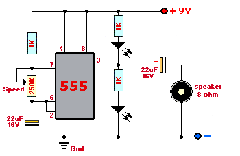
Now the scheme:
To build your metronome, you have to follow this scheme:
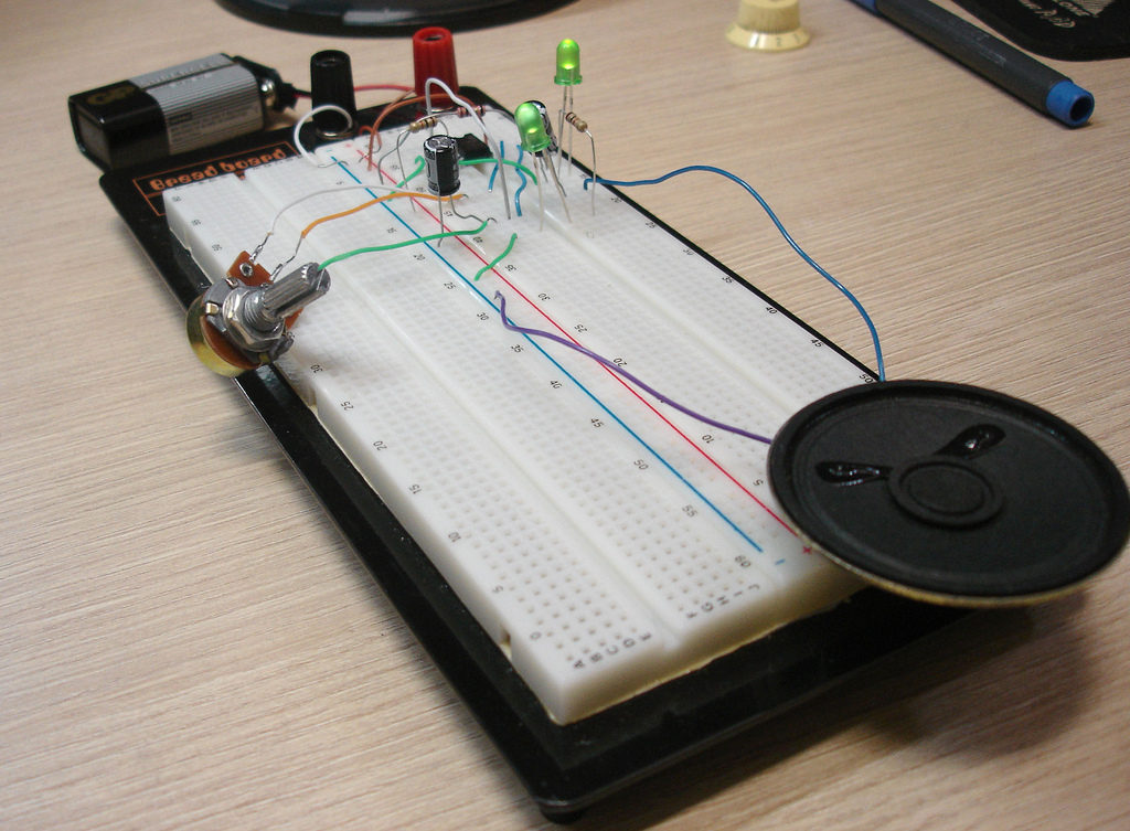
Pictures and Videos:
The circuit I made isn’t so beautiful right now, but it will be cute as soon as I assemble it in a read boar, then I will update this HowTo.
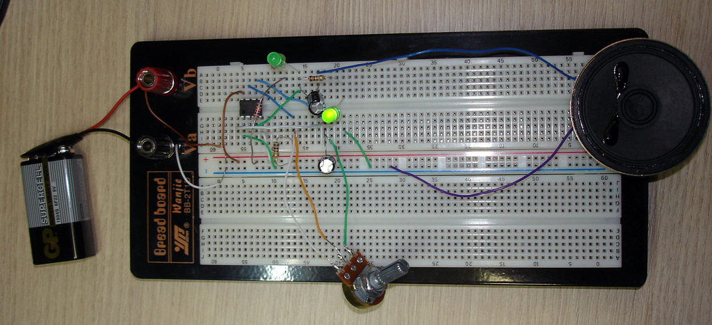
After you have all assembled, just turn on your circuit and you will see and hear the beats, where you can set different speeds by chancing the resistance from the 250K potentiometer. Now grab your guitar, or whatever you play and go practice with your new metronome. 😉
I hope you could understand my HowTo, if you have any question, just post a comment with the form below.
Thanks for readying!
good thing, but you can’t never have a 200 ohm cap.
oh yeah and you don’t change the value on the cap. you change it on the pot
hello Danny
trying to get a metronome light practicing device constructed looking at your video just heard about arduino so trying to build it now, its 13 lights that reperesent the 13 notes to practice scales.
That sounds fun! Share it with us when it’s done! 🙂
Oddly enough, you can have a 200 ohm cap 😛 It could refer to a couple different measurements, for example the reactance. Xc=2pifC, (IIRC), it depends chiefly on the frequency.
Neat metronome…
I only have one nitpick about your guitar playing: Try to not have your pinky tucked in all the time (my music teacher is always on my case about the same thing).
@Danny Antakli: Thanks man! My mistake, of course you can’t have 200K Ohms capacitor, 🙂 Just fixed.
@Sam: yeah! I don’t really play guitar in like 2 years 🙂 But thanks for the tip 🙂
Excelent! good cicuit.
hi daniel,
i’ve been wanting to make a few metronomes for friends for a while, and found your tutorial in my search. great job. and thanks.
cheers,
roy
nice job! I noticed Iron Maiden: The Trooper. Good song, fun to play too.
thank dude,i made my frist metronome with no skill in this feild at all and with about 40$( that inculeding the wire kit and bread board) plus abut 5 hours looking at your fuzz and one sized pic.
I me a noob, so the diagram was basicy unless.
i toke some CLEARer pic hehe; i hope to sent them in.(flicker i think)
I think i used less wires then u, now i need to learn how to sodera little board.
thank again
I have an electronic drum machine (Boss DR-220A) and am interested in this project to use as a foot operated ‘trigger’. (it is hard to turn the drum machine on and then start playing my guitar) The drum machine accepts a 5v signal (beat) that triggers the rhythm pattern to play.
I think I could use your circuit with no speaker – just run that output into the drum machine with a footswitch to start/stop. I wonder what voltage is coming out of this circuit (to the speaker) or if I should use 4.5 volts (two 1.5v batteries) to power this to get closer to 5v out at the speaker. Or perhaps it does not matter…
If any of you have advise/suggestions, I appreciate hearing them!
Sid
Thank you very much!
By the way, this is the first working circuit I built which has a speaker on it but no microcontroller 🙂
WOW That… Is… AWSOME!!!!!!!!!!!! I did that, but I screwed up the wireing 3 times until it worked!!!!! Although, how can you change the sound affect??? : )
I made It it is awsome!!!
REPLYYYYYY
please????
Well, it’s a bit harder to make it sound in a different way using this scheme. If you would like to learn more, you could make one using a Arduino. Then you can make any sound from it! 🙂
Daniel, vc poderia me dizer cmo eu identifico o numero das pernas do CI? d qual ld começa a contagem?
Hey rodrigo, you can identify where the IC pins “start” by looking for a semi-hole on the top. You can follow this example: http://www.orgonecentral.com/zapperguide/555pins.gif
thanks..I asked cause Im going to make a circuit for it..thanks again
Hi, im a AP Physics student in my high school and we have to build something for a end of the year project. I decided to build a metronome and found this page during my research. It is the best how to by far i found but i cant find anywhere that explains exactly what the different parts do (i know that the resistors make resistence and V=IR and that stuff) but like how they function together to make the variable speed metronome would be a great help to me. So what im asking is maybe if you had some extra time could send me and e-mail or post a thread or something going into more depth than just the circut setup i would be very very very grateful. You can put in as much depth as you want or as time allows, anything will help. But dont forget i am still a high school student. Much thanks.
I think to be a little more specific i wanted to know how you put it together from scratch, why did you connect this to that and whats it fuction as, etc, and how you knew to put it there
@Rodrigo, good luck man! 😛
@Cal Yes, I think I have a good .doc file explaining how things work there. If you want, just send me an email from CONTACTS.
Can I also get the doc file explaining it?
hey just checking up on the e-mail making sure there wasnt a sending problem or something. Ill be waiting, thanks.
The Arduino Sounds interesting, would it cost alot?
Arduino isn’t exencive! Take a look here http://www.arduino.cc
Or use PICAXE, it’s much cheaper than Arduino! 🙂
Hey! I’m in a similar situation as Cal. I’ve actually alreay built the circuit but I’m having a hard time making it work. If you can send me that .doc file too, it would be great! Thanks!
eh so umm how about not audion metronom..i mean with leds only 😀 is it possible??
Please send me the doc you talked about. I don’t see the LED’s in your schematic. Also, there are two capacitors in your schematic but only see one capacitor in the photos. What’s up with that?
It is fine if you want to do it for fun… but with about 10$ you can buy a digital metronome, with much more precision… 😉
Hello… I was wondering if you had a multimeter and could check something for me. When no sound is coming out of the speaker, is the Voltage at pin 3 0?
Asfastasdark, I can’t do it right now, but when I connected the output to the oscilloscope, the sound happens when the signal goes down or up.
The schematic as shown doesn’t oscillate with a 50% duty cycle, meaning that one LED is on for slightly longer than the other. Of course, this is only noticeable at very high tempos. For example, when the 250K pot is down to 1K, one LED will be on for twice as long as the other. There’s a circuit in the 555 datasheet that shows how to make it oscillate with exactly 50% duty cycle regardless of the frequency.
Hi!!! very good!! I am Brazilian and I liked project… I made it and functioned!!! great!!! thank you guy!! mail me!!! God bless you!!!!
Hello everybody, I’ve built the PCB this metronome, if anyone wants it please contact me
herberthturcios@hotmail.com
greetings from El Salvador
what if i decided to put a volume knob for the speaker? how should i do it?
Hey this metronone is pretty slick!!!I’d like to try it but i’m not good at reaing schematics so can you please upload the .doc file or send it to me please
PLEASE!!!!
PLZ!!!!
@Vignesh, I don’t have the file with me, but what you can do is take a look on how the IC 555 work, that’s a good beginning. =)
Hi, will these capacitors be OK? http://cgi.ebay.co.uk/ws/eBayISAPI.dll?ViewItem&item=270279772936&cguid=33507e2d11f0a0e203410041ff601354
Please answer :), want to complete this circuit. You’ve been a great help so far.
@nigvesh, sorry for the delay, yes, they will work =)
hey this is really good, but im struggling to work out what holes each component goes into? im not clever enough to work it out from the diagram :p
Thanx for the circuit. It was perfect for me. Simple, Cheap.
Hi! I’ve just built this scheme and it worked, but I got a little problem. I’ve got one led lit all the time. I mean, there would be only one led lighted on each beat of the speaker, but there is one always on (the onde between 9V and the 3 pin node) and the other goes on and off at each beat. Would you give me some help?
Can i use another pot value? I couldn’t find the 250k ohms around here, only the 330k ohms. Cant I use a lower value, like 150k or some comercial value around this point and associate with a static value resistor? Or just use a lower value pot without association?
By the way, thanks for the project! It’s going to be very helpful for me.
hiiiiiiii
Hi, I am living in Holland and saw your metronoom and i like it.
Did you have a drawing of the PCB?
Thanks in advance!
Andries teunissen
@Andries Sorry, I have not made one for this project!
You can try Eagle Cad and make your own, it`s fun! 🙂
Daniel, vc poderia me dizer cmo eu identifico o numero das pernas do CI? d qual ld começa a contagem?
hey, good work.
can i use this circuit without teh LEDs?
@paul sure! =P
May I know which pin of the 555 goes to the ground? Is it pin 2 or pin 1?
this is great! thanks for everything… 😀
Any particular reason you chose an 8 ohm speaker?
According to this website:
http://www.kpsec.freeuk.com/555timer.htm#topofpage
64 ohm is the minimum…
Hey i’m currently building this but the potentiometer when i change the setting up or down causes my 555 chip to blow is there anything i can do to adjust this i.e. an extra capacitor or resistors… thank you
Nice! It would be work with 12 V “battery”?? Or what need to change in this schematic to able to that??
I put one together this evening. Your circuit diagram is great but the breadboard layout isn’t.
Great little project, thank you.
This circuit is incomplete, and DID NOT work when i tested it. Please correct so others do not suffer through the frustration that i went through.
thank you
@Dr it is NOT incorrect! :0)
how could I use it with headphones?
Thanks
Sure you can!
Which is some inspirational stuff. Never knew that opinions might be this varied. Thank you for all the enthusiasm to provide such beneficial information here.
This schematic it’s not wrong, but you need to connect pin 1 to ground for this to work. And the schem omits de pin number, so it’s easy to omit that connection and have no sound.
Hi 🙂 Great project. THX. I’m working an a simple design interaction project and I was wondering if someone can help modifying the circuit for my needs. (This circuit is as close as it gets to what I need) I need the metronome to work as a audible clock making the “TIC TOK” sound in a one sec. intervals. and every one hour (3600 sec. or 3600 TIC and TOKs) a LED should work for one min. (60 TICTOKs) and be turned off. The 2 LEDs in this projects are not needed. Can it be done with this circuit? Thanks all, ET
Is there a problem if I use 1k8 or 1k2 resistor instead of 1k? thx
Hi I am going to make this circuit but i am also going to put a headphone jack in. How could I do this?
Hi,
how can I do it with one double color diode? is it possible?
Hello Daniel,
Appreciate your ‘How To’ on building your own metronome on http://www.danielandrade.net/2007/11/01/howto-make-your-own-metronome/.
I need to put this to a slightly different use as explained below.
Being a musician it is obvious that you are aware of the importance of proper timing. I am a steel guitarist and I play in a classic country band. What I want to build is a SILENT metronome (LEDs only), but a little different than any I’ve seen. My idea is to build it basically as you have diagramed, but without the speaker (or put a potentiometer in line with the speaker so as to be able to silence it when performing for an audience) and incorporate 3 or 4 output jacks on the unit. These output jacks would be standard 1/4 inch phone jacks so standard guitar cables of different lengths could be used to connect the remote units to the controller. The idea is to be able to make separate enclosures which would be located primarily at the drummer’s location and the bass guitar since these are the instruments responsible for maintaining a steady beat. These LED units should flash simultaneously so as to provide a timing mark for each musician’s location and I would prefer to use 10MM LEDs to make them more visible. Also, these could be ‘daisy chained’ as long as there is no difference in the times at which the LEDs flash.
I have a block diagram to illustrate what I’m trying to describe but unable to post it here.
So, what I’m curious about is whether your current schematic would be adaptable to such a project, or would it take something different.
Looking forward to hearing from you and keep up the good work! You’ve provided a lot of fun and useful projects on your web pages.
David Black Sr.
i dont know to play the music instriuments so shall i put any music for that the ckt vl work ………….ple help me
Hi Daniel, thanks a ton for the circuit, very helpful. Could you please tell me that how did you select the value of the resistor/capacitor/potentiometer/speaker etc. What I am trying to ask is that how did you know that 1kohm resistor or 22uF resistor has to be used. Are the values decided by trial and error or is there some other mechanism based on calculations? Please help, thanks again. 🙂
Hey Gamini, what you can do is take a look on how the 555 IC works. It’s configured as a astable circuit, that will oscillate with the frequency of the RC constant. You can get more info on how to calculate all the parameters here: http://en.wikipedia.org/wiki/555_timer_IC
Daniel, tem como disponibilizar o esquemático do circuito, por gentileza?
Opa, desculpa o problema, acabei de arrumar 🙂
Is there any way of changing the tone of the clicks. I have a digital pendulum clock which strikes Westminster on the quarter hour but unfortunately doesn’t have the clock ticking sound and I just got the idea that I could add a metronome but would like a deeper sounding click.
your method is really working in making the metronome but is it possible to make metronome by using potentiometer of less than 200k http://bestmetaldetectors.net/