Listening to music on my PC (proudly using WINAMP), I was wondering how it would be to have some LEDs blinking with the sound that came out from the P2 connector. So I decided to make a simple circuit to do that. It worked pretty well, so I decided to write a post with step-by-step instructions on how to do it. Hope you enjoy it!
Material and Equipment:
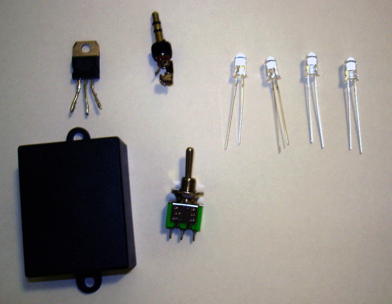
- 4 LEDs (any color)
- P2 plug
- 2 position switch
- TIP31 component
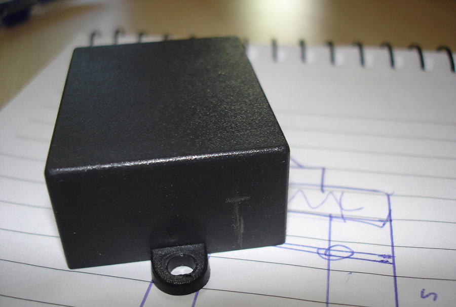
- Box to put all the stuff (if you want)
- Soldering iron and accessories
- Cable
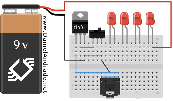
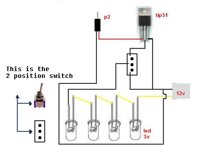
This project will work like this: you connect 4 LEDs in the +12V from your computer, they are soldered to a 2 position switch that will connect to a component called TIP31. This component gets the intensity transmitted by the P2 connector, and with that, makes the LEDs blink with the music.
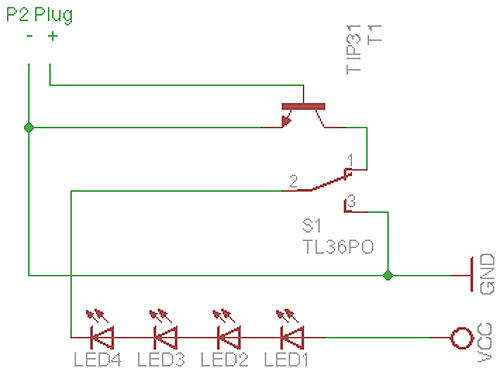
You can follow this schematic (there are 3 different ones to help you understand it).
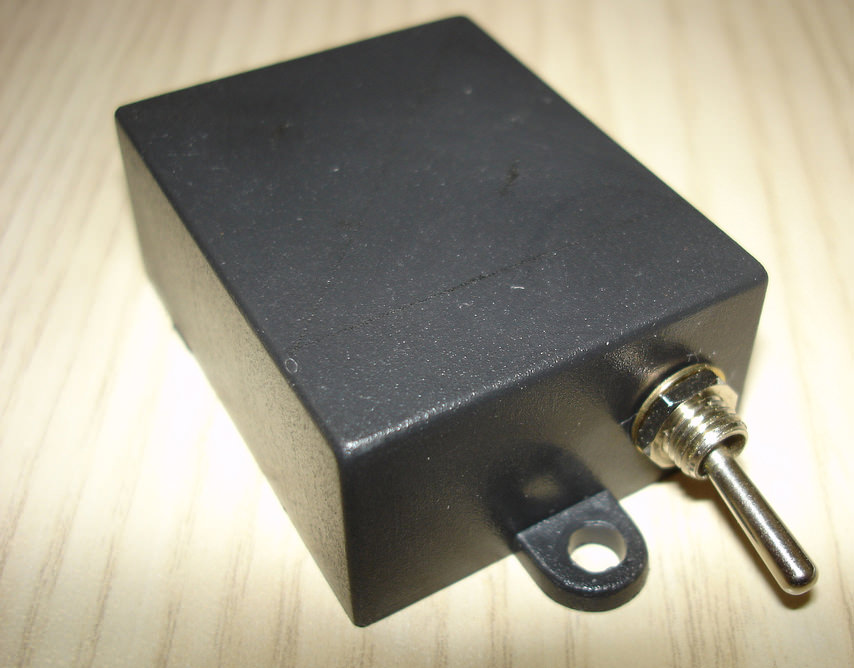
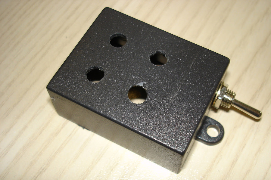
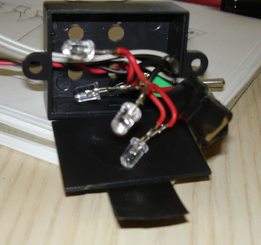
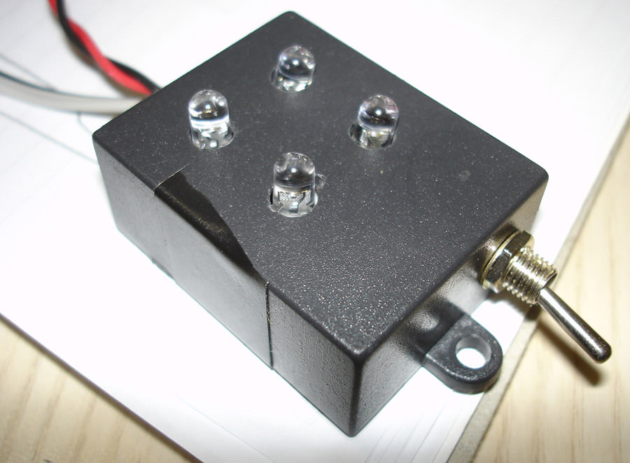
For this project, I decided to install everything inside a small black box I had here and made 6 holes in it. Four in the top for LEDs and one on each side for the switch and cables. You can follow the pictures:

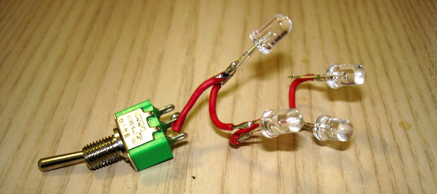
With the box ready, it’s time to connect everything. I started with the LEDs, soldering one small cable connecting each one, so it would be easier to arrange them inside the box after.
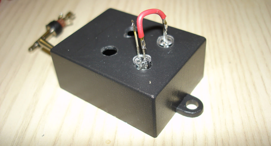
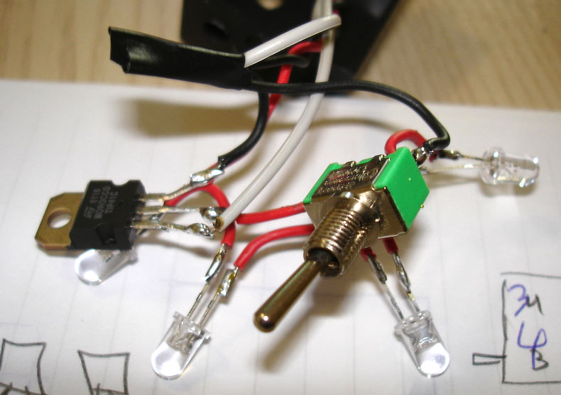
After connecting all of the LEDs, you must connect the cable coming from the LEDs to the center pin of the switch. One side of the switch goes to the middle pin of the Tip31 component, and the other one goes to the ground cable.

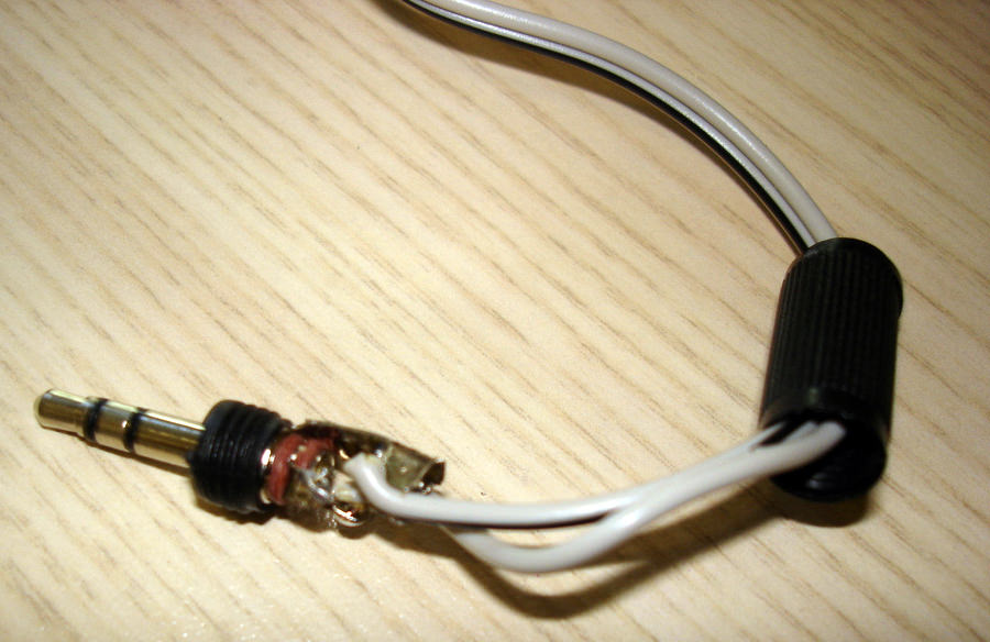
Now it’s time to make the P2 connector. You can see that the P2 connector has 3 pins, they are, left channel, right channel and ground. So you have to decide if you want the left or right channel and then connect it with the left pin from the Tip31. Remember that if you connect the P2 using the left channel, only the right is enabled on the computer and this circuit won’t work. Usually the ground pin is the bigger one, and the others are small and similar. You have to connect the ground from P2 connector to the right pin of the Tip31 (right pin from Tip31 is ground)
On the other pin from the switch, you must connect it to the ground from Tip31. If the switch is closing the circuit with the Tip31, the LEDs will only blink if there is a signal coming from the P2 connector, and if it’s in the other direction, the LEDs will always be ON.
Now it’s time to put everything together in the box. As you can see in this picture, it’s not very organized, but after closing the box, it’ll look much better.
Job is done!!


I’ve recorded a video with my first test of the blinking LEDs. You can find it here.
Obs: In this video, I made it with just one LED to see if it would really work.
You can download the video of the final job HERE.
Here is the video of the finished project:
I don’t know if I was clear enought in this HowTo, I will re-check this in some time.
If you liked it, have any corrections or advice, please leave a comment!
Thanks for reading!
I don’t see any images and I’m way to much of a novice to get it with just the text. 🙁
anon, I wonder why you can’t see the pics. Try to see if your browser is blocking any outside picture, because all of them in this howto are hosted on my flickr account.
Wow this is sweet…cheers Pasterler0
Any way you can post the links as to where you got the equipments from.
thanks
Wouldn’t it just be easier to set up your projector to shine Gforce http://www.soundspectrum.com/g-force/screenshots.html into your case. Gforce dances to the music better than a couple LEDs do.
What IS the music that accompanies your flashing experiment? I must have it!!!
The project is elegant in its simplicity – DUGG!
Hey, nifty idea. Have you thought about putting some kind of timing chip in there, or a potentiometer to have them produce different effects? How about some sort of sound resistor, to completely remove the need to plug it into your soundcard at all. 🙂
Best wishes and neat idea.
How about a circuit diagram using traditional electronics symbols? Would be much easier for us old-timer EEs to read.
sound resistor…you mean like a microphone? 😛
yeah wouldnt it be easier to but a $1500 projectors and project a lame screensaver in there…
geezus the lame comments and spam you find in coments…
GReat job.. love the tutorial. KEEP IT UP
Awesome project! You have inspired me to create one for the audio montior out on my home reciever.
Nice post. Good project for those new to electronics.
Nice!
I like it, but could be great if we can share the plug connector, because I only have 1 sound output in my pc.
Leandro, you can actually use a P2 “T” (as we call in Brazil) for that.
http://ovelha.org/pasteler0/files/images/posts/p2-t.jpg
Bright, the song I used on that video is Orjatar from Teräsbetoni, a finnish metal band!
well i try to build one of these, but i’m having issues. the whole system works, but my led is extremely dim. I have one hooked up with a resistor, and had four and no resistor and same problem. also it works for about a minute, then stops. if i unplug the p2 connector and plug it back in, it will work for another minute. can you help? thanks!
oh yea, and i know that it isn’t a problem with the led. i’m thinkin maybe i got a bad tip31? if you could help, i’d appreciate it. thanks!
axsys, I’m not sure what is your problem, maybe its the TIP31. When I was making some tests, my TIP31 just stop working too, so I had to replace it. You could get another one and try again.
well im ashamed to admit it but the problem was user error (i had it coming from the red power wire not the yellow, i think red is 5 volts?) anyways, it looks awesome. thanks for the tutorial, and if you would like to see a video of my lights in actions, then let me know. thanks again!
axsys, I’m very happy for your project, congrats man!! And yeah, I’d like to watch your video!!! 🙂
I wouldnt mind seeing some more videos, maybe a bit better quality. Im planning on giving this a go :S
Damnit, Sorry i didnt see the second link 🙁
Also, What would you recommend, Left or Right audio?
Aidan, I’m not sure wich one is better, I think both its ok! 🙂
Ok im kind of new to modding. But how does this connect to the computer? Im trying to work it out fromt the pics but can’t.
lol 😮
K, you get the P2 connector and plug in your computer Line-Out. But if you wanna listen and see the effect at the same time, you can plug your speakers P2 and the projects P2 on a “T”, like this: http://ovelha.org/pasteler0/files/images/posts/p2-t.jpg
I ended up using a splitter like this:
http://us.st11.yimg.com/store1.yimg.com/I/xcom_1876_647298
that way you can cut one of the female p2 connectors off and just solder some longer wires to it. i ran everything into a circuit board that i stuffed inside a little box from an old cold cathode convertor. one of my cold cathode’s went out, so i took the plastic bar from it and drilled a hole in the end for an led to fit into. now the tube lights up from one end with my music, and the louder the music gets, the more the tube glows(looks like a single bar on a VU meter). i tossed it all together with some cable sleeving and its looks really good. I’ll try to get some pics and videos up soon.
I wonder if this is possible….
Take the output from the PS2 connector, break the audio signal into its component frequencies, 31hz -> 16kHz and send each isolated frequency to an individual LED so that you’d have something looking like a graphic EQ!!
I have been thinking about doing something like that for awhile, but still cannot figure out how to isolate individual center frequencies before sending them to their respective LEDs…
-adam-
adam, I found on internet sometime ago, one small piece of software, that you connects the leds to the serial port and it will make them blink the way you want. I’m not founding it now, I’ll take a look later.
On your chart here: http://static.flickr.com/35/70733363_7bc5873491_o.jpg you are showing 2 wires going to the 12V. Is this the computer power itself? If so, where would i connect the wires to the power supply?!
HiddenS3crets, sorry, I’m not sure if I get what you said, there is 3 wires going to the ground of the 12V connector. I got the 12V from a molex, so you get the power from the computer for this.
Would it be possible to do the same thing (blinking leds) but connect them to the serial/parallel port and use a winamp plugin? I don’t really like that the soundcard has to give power to the leds…
well after a couple weeks of my leds working, they all of a sudden stopped functioning correctly. they will no longer light up with the beat of my music; however, they will still turn on then i flip the switch to always on. my brother, being an electrical engineer, said that i probably blew the tip31 because the power from the right channel needed a resistor before it went to the tip31. is that true?
axsys, I’m not sure about that, because the Tip31 just closes circuit to lightup the leds. But it may be true, sorry, can’t answer that. :/
Excellent how-to, but I was wondering how many LED’s could you connect in series to a 12V source. I’d like this to light up more than just a PC case.
The way I have the circuit hooked up (the same as the diagram I think), the led’s are receiving constant power from the battery source. Is there something else that should be happening here?
Sorry, figured it out… the schematic is confusing because the way the leads of the leds are drawn I thought they were hooked up only to the ground, rather than only power.
Cool idea, Pasteler0! However, I have had a few problems with LEDs being dim or burning out with the circuit you provided, so I created my own variation. I have put up a schematic and a video on my website at http://www.runtimeerror.net/blinky/index.html if anyone is interested.
Brian, hey man!! Good job, I liked very much your work, i’m thinking in make your way, I belive it will work even better then mine! Thanks
Hey, thanks =) I am not sure how well my variation will work with others though. On my desktop, I have a relatively high-powered soundcard and turn up all volume controls to get the best result. However, my circuit doesn’t seem to like my laptop. I will probably move to an op-amp design as soon as time becomes available.
Pasteler0! Get idea man. I seem to be having a problem (apparently with the TIP 31). If the volume of whatever I’m listening to is louder in places, it seems that the TIP 31 wont pick up on the softer things. For example if I turn up the volume and then turn it back down, the lights wont work because the sound is softer… Any ideas?
Finished it, with two channels, and stuff!
(two sides of the tower, used one circuit on each channel. 16 led’s on each circuit, with two led sharing one variable resistor )( so I don’t fry the TIP31… And can make some cool effects too! 🙂 )
Too bad my camera is dead.. Never ever let a friend loan your camera!
Hi, I’m trying to build a circuit like Brian’s. Except I need to use 6 LED’s with a 9 volt power source. Can some one please let me know how to do this.
Revolution: All transistors have a “turn on” voltage, meaning that a signal has to be at a certain voltage before it can be detected and therefore amplified. So, your volume needs to be at a certain level for the sound signals to be detected, and that’s why the softer sounds aren’t audible.
Ray: You can drive 6 LEDs if you put all of them in parallel. I use a battery, so that’s why I only use one or two to have decent battery life.
First of all this is a great site and thanks for the how-to but i havieng a problem the leds ( i used 1.7v RED x4) and put a 220ohm resistor in frount of them (is this needed?) the leds work great on steady power and they at first didnt light up at all then something happened and they are very dim but still no blinking. any help would be greaty appreated
To William
First of all this is a great site and thanks for the how-to but i havieng a problem the leds ( i used 1.7v RED x4) and put a 220ohm resistor in frount of them (is this needed?) the leds work great on steady power and they at first didnt light up at all then something happened and they are very dim but still no blinking. any help would be greaty appreated
Hey, To get the right resistors to use with the leds, u need to calculate the ohm needed for your type of leds, R=(12v-1,7v
Hey, To get the right resistors to use with the leds, u need to calculate the ohm needed for your type of leds, R=(12v-1,7v
Hey, To get the right resistors to use with the leds, u need to calculate the ohm needed for your type of leds, R=(12v-1,7v
Hey.. i’m in the u.k and cannot find anywhere to buy me a tip31 anyone know of anywhere ? Any help would be great.. intending to make one as small as possible( About the size of a pp3) and then could be used with mp3 players and such.. i know you could make it smaller than a pp3 but power is a plus in this project.. lol.
hi, i want to do one of this but i dont quite get the scheme… the power comes from the PC power, that will be the 12V but why the 12V splits in three cables in that scheme? i get that part where you put all the leds together with a cable and then to the middle pin in the switch and one of the pins of the switch goes to the middle one in the Tip31 but then what? where do i solder the and – 12V? i am confused… please someone explain it to me just a bit more in details… i already have all the materials needed. thanks
Ok…I need to clarify a few things first. The P2 plug is just like a headphone jack? And plugs into you computer? And the TIP31 goes where? other than that i understand the setup.
Also depending on what that all does, can it plug into a MP3/CD player?
Hope it works, when i do try…seems like there are a few problems, but i love the concept =)
i’m a bit confused. it looks like it doesn’t have a posotive flow of energy in the schematic, and where do you hook it up to. maybe i wasn’t paying attention but please email me more specific instructions. thanx fullmetal18021@yahoo.com
this is very nice idea, if you’re gonna look at the schematic, it looks very easy to construct but when we construct it, it doesn’t work… the LEDs are working but it does not blinking…… can you explain more of this nice project….
Hey Brian!!! is there any way you can send me some pictures of your LED set up it looks a lot better.. but i cant understand exactly what you did, if you could send the picutres to ballpointdude@hotmail.com that’d be great. You probably wont get this but if you do please send them! haha thanks again
looks cool, i’m gonna put a few in my MAME.
Nice man, show us when it’s ready =)
i used a tip41 its stronger so it helps alot and i also added a three way switch so it can do:
1. On
2. Music acivated
3. Timed using a 555 and a pot
ee, show us the final work.
Hi!
I wanted to ask something:
Will all this work if I do two circuits and connect 1 to the “right channel” of the p2 connector and the second circuit to the left one…?
It could be very nice.. 4 blue leds for right channel, 4 red leds for left channel…
DimaX, yes, it will work!
Thank you very much pasteler0 🙂
I might try it!
btw, your work is great and THANX 4 the gr8 guide!!
I tried to replace the TIP31 by some other transistor .. BC548C
works but kinda weak .. the leds turn up only whe the music is very loud
how do you think if i chenge the voltage from 5V to 12V .. it will be better ?
You have an awnsome blog i liked the howto’s and the mods *thumbs up* !!
hey i did everything like on the schematic except that i used 20 leds in parallel
…buttttttttt………
1. on my mp3 the leds are very dim
2. on my pc they are always on with NO BLINKING
i use a 12V power source
tried 5V still the same 🙁
This is a pretty sweet project! I bet you could pretty easily hook this up to some high duty inductors and beef up the transistor and use a whole string of christmas lights instead of LEDs >=D
I like this one alot, I made one and it worked, but then I decided to perfect it (although this is pretty amazing) so I took a battery pack box and added 2 lights for the low sound and 2 lights for the high sound, how I did it is just create 2 sets of the same device and put it into one box,
my sound card has a low pitch and high pitch port,
when I hooked it up this thing looked pretty cool!
you guys should try it or even perfect this one!
Hey nicholas, that’s a very cool thing you did. Is there any chance you could show us some pictures or videos? =) Good Work
Hey, Awesome project!
I’ve been working on this for a while, and still couldn’t get it right.
I am trying to build onto this project into making Christmas lights correspond with the music since
its Christmas soon, but im having no luck. I even bought greater high current applicable transistor
and everything. I wired the Christmas lights into the switch and it works fine. I have made it so
I have to plug the socket into the wall so I dont have to deal with the problem of buying new high
powered power supply. I am having trouble with wiring of the TIP and/or to the switch that has only
3ends. Sorry, Im a Newb at electricity and my questions will probably disturb some of the people. Pasteler0 can you make a how-to of making christmas lights blink with the music if possible by any chance?
Put a small (200ohm or so) resistor in series with the LEDs. Your design is bad as it is right now.
Actually, you need a few resistors in that circuit. Geez…
No, actually this is a very good Idea. dont knock it.
I actually was messing around with this idea a little bit, each LED has resisitors each different sizes, so I tried it and each light lit up to different beats and sounds, so I thought that was pretty cool,
so then Im like hmm how can I make this better, I came up with adding capaciters the biggest capacitor went on the smallest resistor and vise versa, so then I tried that, and now its so cool,
when I play a song each light still lights up to its own beat but now they fade out, the higher beats fade faster and the lower beats take like a 1/2 second longer!
see what you can come up with
Ill post some pictures Pasteler0
here are some images Pasteler0 hope you think there cool
can you post these on your site sometime?
oh sorry thoughs didn’t work
here they are
http://www.fasterupload.com/out.php/i678_03.jpg
http://www.fasterupload.com/out.php/i677_02.jpg
http://www.fasterupload.com/out.php/i676_01.jpg
ok you mind posting these on your site so everyone can see?
Hey man, where are the pictures?! 🙂 You can post them on http://imageshack.us/ then show us the link.
tried to make this thing light just stays on all the time i got th tip31 part at radio shack can any one help
Hello Dima,
If you are trying to make it so the lights stay on you don’t need a tip31,
sometimes schematics arent easy for province but if you mess around
you’ll get the hang of it, and make sure your lights voltage adds up to
12v or lower,
I my self are using a tip41a, its alittle stronger but I like it because the
the lights tunr of alittle more often but in my opinion looks cooler.
good luck Dima
Hey pasteler0 I figured out you only need the 1 wire from the tip going to
the p2 if you hook it up to a stereo, :), just some I thought was cool,
Hey, i was wondering, could you possibly do this set up via usb? I currently am powering christmas lights through a usb cable and was wondering if you could make them flash through the usb?
Plz email me.
insanesquirle@gmail.com
Do you want to make them flash with music? Using USB you could use it’s 5Volts and then connect to your P2 output. For making them flash only with the USB port, without the output, you would need a software too. =)
Thanks, how would i connect the p2 plug to the tip31?
Hi!
Ever tried to read smth about current limiting resistors, which should be added to this “lovelly circuit” for it not to be able to blow your transistor/leds/sound card?
Try googling for “electronix basix” 🙂
Otherwise this circuit is quite a beast (w/o those resistors, i mean).
Never thougth this would work, things never work for me but this did! Smart idea and nice guide, easy to understand too.
hello pasteler0,
I’ve made the device according to the schematics you gave although I slightly modified it to include a switch that could toggle the left and right channel inputs from the p2 jack such as when the right channel is selected, the circuit does its job while it turns off and acts passively when the left channel is selected.
I have a few observations though. First was the first LED was off. I don’t know if it’s busted or not. Since it is connected in series with the others, an open LED would definitely cut off the power for the remaining part of the circuit. And last was that the LEDs don’t light up at the beginning of a song specially when the PC was recently turned on. Could you help?
where in the computer am i going to connect the circuit?
thanks anyway for the site.. it’s pretty challenging
hey, where do you even GET the P2 plug? if you can get it online, can you please post a link? tried looking EVERYWHERE! right now im resorting to taking apart old headphones just for this >
Hey freakout, you can get a P2 plug in any electronics shop in your town.
This is pretty cool idea. I just post on other blog about LED controller. I think if we develop with this design, we can have more option such as changing color and chasing color or mix color somehow. I just got all these idea from
http://www.lunaraccents.com/technology-programmable-LED-controller.html
This website is pretty good but they will take so long time for the prototype. It is better just to get some idea and work on your own!
Hi, I managed to get this circuit almost perfect 🙂
This fixes the problem where leds go dim and off after a while:
You need to put 150kOhm resistor from the leftchannel to the led plus/powersupply.
I welded old N-Gage headphone plug in the circuitboard and used old N-gage recording cable to get sounds. I took power from usb.
But still the leds wont light if u put volume to the max and then put it low.. It works as long when u dont touch the volume 😛
If there is no sounds, the leds light up.
i can’t figure this out, can someone please post a detailed picture of their completed led sound blinkie. I really want to put this in my car, but I’ve been two whole weeks here and there trying to figure this out. I am going crazy with this. can someone please draw a layman’s type diagram
TearTox, please, show us some pictures of your project. 🙂
SOOPERGOOMAN, I’ll try to make the scheme, soon I’ll post here.
Hey all,
In response to the questions about different LEDs for different frequencies, if you have a decent/modern sound card, you can make two different curcits…one for your subwoofer and the other for your front speakers. This will make them flash to the different frequencies.
Well, I think this would be a bit harder, try to apply a similar scheme to your subwoofer, install it in the place where it receives the frequences from the computer, may work, but I’m not sure.
If you do so, please, show us the result! 🙂
Hey there, was wondering, if I connect the P2 jack into the headphone jack of my computer, where would the audio come out from? Wouldnt it just light up without the sound playing in the background? All i understand is that there wont be any loud music when I play a song, but just a couple of flashing LEDs?
Cool project, I like it.
Well done
Hello Pasteler0,
i tried to make that circuit but it just don’t work.
The guy in the store gave me TIP41, is that matter?
thank you.
i made one of these, but for some reason they don’t blink, they only stay lit. do you have any idea why its doing this. great project though.
peace
can you tell me where you got the 3.5mm plug or p2 plug?
My circuit works, but the lights barely flash to the beat. Once connected via this ‘P2’ plug, the LEDs illuminate….not at full intensity, but still bright, so there is not much of a difference when it recieves the audio signal and brightens even more to a beat…
The difference with my circuit is that I am using 3 LEDs hooked up to a 9v battery. Could this be the problem? I am trying to aviod using 12v.
hi! this is a very cool stuff. im kinda amature with circuits. i just want to ask about the 12v output. correct me if im wrong is the yellow wire in the diagram is also the same yellow wire in the molex of the power supply? and how about the black one? kind a bit confuse.
thanks in advance! ^_^
hey dude, so can you use a tip41 for this? or does it have to be a tip31????
i want to know that web camera wich connect computer with out wire. and that camera is 1kilometer frome the computer but connect with computer with out any wire
Dilphat, I belive you can do that! 🙂
muz, sorry, I didn’t get what you’re saying…
I can’t get this. I do all that the scheme says, but it still don’t work. the lights work if I turn on the swich, but wont work if i turn on the tip31
Hello c0braz, you should try to put your sound output louder. And see if it works. You can also install some kind of transistor to boost signal, but then I cant really help you yet. I’ll make another blinking leds scheme sometime with more power.
Anything just say! 🙂
This is funny no Resistors are all. you can’t do it.. unless this is high powered LEDS. i mean you can blow leds just connecting stright.
i don’t see how this works with out. resistor and with out proper voltage supply to led/transistor
where do i connect the p2jack????
hey what ever happens my comp wount got screwd up right?????
just want to be safe
Ryan, You should connect th P2 Jack on the computer.
You have to be careful to not cause short circuit, besides that I belive there’s no possible harm to your computer 🙂
will this work for a laptop or is it stricly a desktop thing
oo and if it does work can i connect it to a usb and will it still falsh cuz i wanna make this a present for a friend of mine…gracias
Hi! I want to connect a cold cathode light to this circuit. Is it possible? And how I can increase the output of my minisystem, because the blinking-leds doesnt work with it… Sorry about my bad english, Im from Brazil…
Thanks!
@JuanS131 It will work from a USB if you make the circuit to worth with 5V.
@Bruno I’m not sure it will work, because I believe the cathode needs some extra energy to power-up. But you can try! 🙂 And don’t bother with your english, I’m also brazilian 🙂
Hi! I connected a cold cathode light to the circuit, but the light blink to weak…How can I increase the power of output of your system?
I will put some videos of my blinking leds working in my room on youtube..
Thanks!
hello 🙂
i am saleh from jordan, really im so happy to meet u.
just i wanna thank u for amazing project. but i try it in my home with extarnal power supply (+12) but does not work i would like to ask that the (+12 v dc) it must from my pc only. or what??
with regards,,
Would you know how to set up something similar for the car radio or even for a stereo in a bedroom?
what would be cool is a video of how brian put his version together
i made something like this go to- http://www.lochtefeld.rocks.it
i have 12 LEDs
Hey, i have wanted to do this for a long while… but a slight variation. what i would like to do is have the blinking LED’s to sound coming from my computer, i want to do the dual channel thing, i would like 1 color of LED for left and one for right. I DO not wan to risk blowing my sound card, so what do i need to set this up with both resistors and both channels?
ill try and be more specific. I want to take on of the mpy port face plates and put 4 led’s in it, 2(red) right channel 2(blue) left channel. i understand the schematic on this page, but i do not understand how to throw a second set of lights in there. I also really like the idea of the resistors, and i liked how smooth the other video looked. (brians) so if anyone could tell me how to hook this up… i would be very grateful.
TheTeZ,
I suggest you use 4 LEDs (3v LEDs) in series (in a line). If you don’t, the 12v source will blow out your LEDs. My project I used 12 3v LEDs. 8 for each side. In addition, you’ll need another TIP32 transistor. For more details go to my project page:
http://www.orephik.com/projects/LED/index.html
~cheers
Er sorry, TIP31 transistor.
orephik Thanks for the link! TheTeZ just follow orephik’s guidelines 🙂
thanks, umm is an LM317T the same as a tip31? it is an adjustable voltage regulator…
i dont know too much about resistors regulators transistors and the such…
hi,
how many LED’s your computer cabinet is lighted With ?
do you have any info on Making such glowing comp cabinets?
Also
Hey guys,
attempting to do this in stages but cant even get it to work with a battery and no switch. The circuit works without using the P2 as shown here:
http://img296.imageshack.us/img296/1999/img00881ak8.jpg
but even though i know there is sound coming through the P2 (im using a male-male extension to get it working first) i get no light when going through it:
http://img386.imageshack.us/img386/4267/img00891rz3.jpg
Any help would be great, either on here or to lellis2k@hotmail[dot]com
i a little confused with where all the grounds go, and what to do with the p2 plug. Can anyone help me thx!!
@sunny, sorry, i know the circuit isn’t very clean, I will try to make a new one soon. Well, with the P2, you connect it’s ground on the 12V ground. The ground goes also on the 3rd pin of the TIP and also on one part of the switch.
thanks but one moe question. This P2 plug what is it? Is it a audio jack from headphones. If not where can I get one thx!!
@sunny Yes, it’s the audio jack from headphones! 😛
Hey, I saw this being asked before, but nobody answered it: is the LM317T (it says its a adjustable voltage regulator) the same as the TIP31? My radio shack didnt have the TIP31, so i got the LM317T. They look alike… I tried hooking it up, but the light always stays lit even when the p2 plug is disconnected.
Thanks
This is awesome im going up to radioshack tomarrow and im gettin all the stuff!
@dave, I think it won’t work then. I don’t know how the LM31 works, you could look in the datasheet, but i’m not sure.
what does a tip31 do?
let me try to say this way: the tip31 is a transistor that will let the energy go to the led when receiving signal from the computer soundcard.
Can i use a mono p2?????????????????????????????????????????????
o and thanks for the tip on the tip31 its all clear now
i i had another idea, is it possible to do the exact same thing that you did but replace the leds with a dc voltmeter? Just another cool little toy for the sterio.
could someone tell me what the “ground” of the 3,5 mm Jack is? and is a “Tip31” the same thing as a transistor?
i did it the exact same as you, but the tip31 part of it will not work. also i would just like to say that my tip31 looks different than your, slightly, how do i know if i bought the right one, by looks?
Hey Guys, i have tip32 and tip41a its the same as tip31 ???
I can use them as tip31 ???????????
I was wondering if a pin 32 will work as they are easier to locate in Canada.
Also can you use a 12v battery instead of the computer and a resistor to protect it
i would like to do this project for my car. i want to run 18 leds running off my car amplifier where i plug directly into the speakers. how can i run this this project. i’ve used christmas lights before but when i use too much power (volume) i blow them out.
Is there any difference in power from an ipod jack and a soundcard jack
OK i know your probobly really buisy, but your the only guy i can talk to about this. I have it the exact same what you have, when the switch is in the on position it is VERY slightly dimmed, but if i flip it over to the TIP31 side its at full power, and you can unhook the p2 and nothing will change. I have tried two differnet TIP31’s and the same thing and there is no wires not touching wires there not supposed to be.
Help would be so greatly appretiated
@Derek “Is there any difference in power from an ipod jack and a soundcard jack”. Not really,
2nd one: On your p2 output, you should set the computer/ipod to max volume. I’m currently working on a better blink leds scheme. I will post it when it’s ready, too bad I’m really busy with university, but I’ll try my best to post is soon 🙂
anything, if I can help you, just say! 🙂
hey i dont know nothing about this stuff haha but i thought this was cool so i want to try and make it but i was wondering like how or were do you hook it up to your pc??
This is great man,
Just found this site and will continue browsing, came from I’ibles.
I’m pretty new to electionics but I think I could handle this.
I want to connect a load of LED’s, like 60, and stick them around my monitor…
Would this be possible, if so, how?
@brandon It’s hooked on the pc. I’ve connected to the 12v from the power supply and then you just insert the P2 plug on your sound card,and it should work.
@Richard Fosters, yes it’s possible, but you need to use the right power supply for 60 leds. If you are really new, why not start with this 4leds project and then try with 60? 🙂 Good luck man!
dude i cannot find a tip31 component anyware is there any other common components that work the same or am i out of luck
i managed to find a ( bt137 component) would it work in place of a tip31 component
Ok Well i have tryed 3 different looking like tip31 components (Dont think tip31 is sold in the USA.) and only one half way worked. i will find the compontent names/numbers and post them later.. is their anyother known compontent?
OREPHick, cn u post or email me a schematic diagram of ur work( http://www.orephik.com/projects/LED/index.html)
with lables coz im not familiar of electrical symbols.. pls help..hirs my email add.. markcatapang@ymail.com.. tnx!
Can you maybe give better instructions ? im trying to make one that runs on a 9 volt battery and have been unable to even start from your diagram and your pictures are not any help either. Is there any way you could do a simple step by step ? It wouldnt need pictures just a nice text document to compliment this would be great. If anyone who reads this has what i need please email it to johnathon007[at symbol here]aol.com
What would a tip31 do vs the tip42? Which one would be better?
Oh, and I don’t understand the battery, if I want to use a 9V battery… Where does it go and do I need resistors to the LEDs? Transistor? Thanks.
I came across a TIP3055 NPN transistor, will this work? Also, if I wanted to hook it up to my Ipod and use a 9V battery, this will work, right?
Hi,
I’ve already got the circuit going just as you designed it. However, I’m trying to get it to work with an Electret Microphone. Any ideas?
Thanks!
@PCMOGU The battery would go instead of the 12v, use 3 leds then =)
@Kelly You can hook in your ipod with no problem. About the transistor I am not sure.
@AlexL There was a circuit somewhere on the web that would do this, can’t remember where. If you mail me I can send it to you when I get back home
is there any way to add additional leds?
Yes you can.
You just have to add another row (in Parallel.) The voltages add in series (3v 3v 3v 3v is what is used here.) So if you add another row, the system will be in parallel and no over voltage. However, the current may be too much for your power source.
Im just wondering. Roughly.. what do you think the cost to do this is?
like, really cheap, less then 5 bucks =)
hey did it. works great. now i want to connect it to my car system.
could you tell me in brief what to do. was thinking of connecting it to the speaker.but not sure how. hope you can help.
Can i use 10 leds with the same components? Especially the TIP31?
looks awesome. going to try soon.
Hey, i was wanting to know if you could help me on a project im stuck with, see the plan is to get atleast 9000 diffrent colored LEDs and convert those into syncing leds and then using a 17’X 18′ plastic board to put on my ceiling, the thing is i dont know if it would run off a 110v connection.
salve voleo sapere che come si chiama il componente tip 31 per pterlo aquistare
compadre el medio aporte hace tiempo andaba buscando algo asi ya lo termine y kedo filete saludos desde chile….
I’ve tried doing a similar project to this, but could not get it to work. The reason, I was told was that the audio output (I was using an Ipod) probably had a smoothing capacitor wired across it, and there wasn’t enough voltage to turn on the transistor. Checking with a voltmeter confirmed that the output was less than the transistor’s turn-on voltage. I assume the author’s computer headphone jack had no such capacitor, so it worked.
It could also be that I used a smaller switching-type transistor, I don’t know, maybe I’ll give it another shot with the tip31.
Jay, you need to check if the ipod’s earplug can supply the minimum current for the transistor to work as a switch. Try the TIP31, if it don’t work, then try with another transistor.
very cool, i ended up using 2 9volt batteries in place of the 12 volt from the PC, and i have 4 extra bright white 5mm LEDs it blinded me for a minute when i was recording it to send to my friends LOL.
very nice work keep it up!
Dan
i just did this project, it rocks i used 24 leds, 12 for each channel, 4 in a series, then the 3 series in parrallel. but the problem im having is the when the volume is more than half way, i get major static in the speakers , they are amplified, and i got the signal after the amp and before the speaker.. is there any feed back in this circuit? could i use a diode to the positive and negative terminal of the speaker to prevent feed back?
seemed to work pretty well. we modified ours for both left and right audio though: http://www.youtube.com/watch?v=MC5GVLcgZUs
hoping this wont blow out my soundcard though as I have heard. im a little cautious as i dont have expert circuit knowledge.
Hi how connect leds in car to the sub woofer?
i did it but something wrong 🙁 when i plug it sound quality is bad 🙁
ehy man….grat job…but i have a question…i’ve got a usb speacker…hoe can i make the same effect without the jack???(sorry for my english…i’m an italian student)
@bigben what you could do is connect the usb pin that transmits the sounds to a oscilloscope and check how is the waves. Depending on how it works, you can make the same circuit!
That looks quite a dangerous schematic to me…
You don’t have a current limiting resistor to then base of the transistor, you run the risk of blowing up your transistor, or the output stage of yous sound-card or mp3 or amp…
Furthermore, you don’t have current limiting resistors for the LED’s. You run the risk of blowing up your LED’s or short-circuiting your 12v supply.
check the basics first…
Yap, this is very intereting.. But.. In local shop with eletronics there si not tranzistors like TIP31C… So, can I use some other or?
If you want to put ony one LED you cand add a 510 Ohm resitence 🙂
I can put a resistor instead tranzistor??
Never mind, I going to near city, so I’ill buy that kind of tranzistor.. Hope will work 😀
can you use this on the scanner light by jest replacing the LEDS with the scanner neon
i have a question.Will this work if i plug that to headphone plug?if it can plesae tell me how to make it work(sorry on bad English)
Patrick said, “That looks quite a dangerous schematic to me… ”
I don’t want to blowing up anything, so can you (or anyone else) help me to make this circuit safer instead of just alerting about the danger?
THX
Transistors:
I have been looking at Radio Shack for other transistors and I don’t quite understand the max power dissipation. I want them to light up with less power so would I want to use a TIP31 with a max dissipation at 40W, TIP120 at 80W or something lower like the 2N3904 NPN at 350mW or something in between? Also, what is the difference between NPN and PNP? Would it effect this circut? Thanks in advance.
@Paul to change de LED brightness, you add resistors, and there is a big difference between NPN and PNP, look at Wikipedia, there are some text about it! 🙂
I am extremele new to electronics and I don’t get it. I set things up like what you’ve stated and illustrated and it doesn’t work. I added an external power so I know the LEDs work, but once I plug it in, A) the music is no longer audible, and B) the LEDs do not blink. How are you getting the audio to play when the P2 is plugged in? I’ve tried 2 TIP31’s to no avail. How can I test them?
I’m new to electronics and have built some really lame dancing to music LED circuits, none of which worked very well. This looks simple to building, but I’m not sure what a P-2 connector is or where to grab the 12 volts. Can I sue in place of the P-2 and USB on 5 volts with a standard PNP or NPN transistor in place of the TIP31 and wiring the LED in parallel?
@Joe A p2 jack is the same you connect on your sound card. You could try another transistor if you polarize it right. Each led uses around 1.7 Volts, depending on how many leds, remember to use resistors!!! 😛
Hey I was curious if I could use this circuit with 5v of power instead. Will that still work? I am using MaxM LEDs and an arduino control board and I was going to try to put your circuit in between the two sot hat I can also have the LEDs flash with music. The MaxM LEDs have a max of 5v. Will this still work with the lower voltage?
@rob yes, it wil work, just add resistors to the leds
Now it’s time to put everything together in the box, as you can see in this picture, it’s not very organized, but after closing the box, it’ll look much better.
hey is it possible to use any old earphone plug for the p2?
Dear DanielAndrade, i was wondering if you could help me. i’ve wired the whole thing as you’ve show. the leds light up fine when the switch is on position 2, the lights are static. but when i put it to the first position it turns of. i have some really heavy metal music playing at the loudest possible volume and i manage to get it to light when i connect the black from the led to the third leg of the tip31. Is there a simple way of testing weather its the tip31 or the p2 plug.
Thank you
Ahmed
Hello its me again. just thought i’d give you an update. I took back the Tip31 today and also bought a brand new p2 plug instead of trying to splice an older one, and i’m very happy to say that its all working now. Thank you very much once again for this guide.
hey i followed all the instruction and its working. but not good in my pc though because the lights where very dim if i connect it to my pc. when i connect it to my iPhone the lights were bright enough…
any help?
@rymond i faced a similar problem. try turning the volume from the taskbar of your pc to full and and use the volume on your speakers to adjust the volume. also remember the brightness of the led will depend on the audio thats coming out. try going on youtube and using it on some of the bass tests that are there. your should see a diffrence.
@Ahmed @rymond it’s because there’s a tiny current that switches the TIP31 Transistor so it let the energy flows flows from the PowerSupply to the leds. The higher volume you set on your computer, the brightest will be the leds. I will try someday to rebuild this circuit with a new and better scheme. 🙂
@rymond i think i know what might be the reason for your situation. ipod outputs its sound in 2 channels ( l & R ). my sound card supports 6 channel out put and when i set it to 2 channel output the leds had a better glow to it. hope it helps. 🙂
@DanielAndrade you know when you rebuild the curcit can i suggest using a simillar transister but one thats more sensetive. thats to say it requires less power to wake up.
lol i made the same thing but i used a Cold Cathode but it didnt worked u think the TIP31 doesnt have enuough power for that??
Looke Here : http://www.fotos-hochladen.net/spa0429idyg7at5.jpg
@Wumpy i think the reason behind your problem is the following:
1. something is not wired right.
2. there isnt suffecient power for the cathodes.
3. you have a dodgy tip31.
if you are 100% sure that you followed the schematics correctly then its more then likely that you may have a dodgy tip31. hope it helps 🙂
Very cool!! Simple but great..
@Ahmed aahh thanks hmm i wired it corectly the TIP31 isn Dodgy cuz now when i turn my volume all up it blinks a lil bit but its not enough^^ not enough Power is the right thing here i think the TIP31 is not powerful enough to get the Cathode full Blinking i think i will order a TIP with more power hmm maybe a TIP120 what do you think about that?
Hello, I am all new to this shit. Have ordered all that I need for this project, but I am already looking at the next one. The tip31 lets power to the leds throug when the volume get high enough. Is there other transistors like the tip31 that has other sensitivities (they lets power throug at different volumes). Then it would be possible to build cind of a volume measurer of some sort. That would be awsome.
Thanks for any answers=)
Is there any difference if i use tip31 or tip31c? Or is it only the max voltage? http://en.wikipedia.org/wiki/TIP31
I useed tip31c for my curcit, as for sound card its an on-board one.
can I use a tip3055 transistor?
Hi Daniel, basing on you layout looks and the Orephik
http://www.orephik.com/projects/LED/index.html)
I carried out a program for making printed circuitsand circuits board (PCB)the following diagram with leds in paralell:
http://img811.imageshack.us/img811/7904/strereoleds.jpg
My doubt is how calculate the transisttor base ressistance (R21 and R22).
Q1 and Q2 is a TIP31 transistor , all ressistances are 510 ohms and the leds with a voltage between2,8-4 volts being the intensity 20mA.
The 3 pins connector is the audio jack stereo 3,5″ 1º ground 2ºL (left) 3º R ( right).
The other connector of two pines is a power input 12volts, that of the positive an the below the negative.
Will all these dataand could calculate the base ressistance of transistor.
Thank you very much closely LUISFRAN
2 position switch which model you’re usana ??
2 position switch which model you’re usana why I bought a not aki but it is equally yours?
can we use a condenser microphone instead of the P2 plug!? if yes can anyone make a schematic so we can all try.. tnx in advance..
Hey! I just started to work with leds, so im no good with em. I just want to ask if you could take better pictures of your project, so i could see all the cables. Im from finland and no good english. Ty!
Well I arranged the circuit, and when I plugged it into my 12v. it blew the transformer.
any idea?
You probably made a short-circuit, take another look at your scheme! 🙂
Hi there:) I have a question about those blinking leds.
how do i have to wire up the leds/tip31/switch so that i have 3 stages:
1.Leds completly off
2.Leds on all the time
3.Leds blinking on music
I want to wire this circuit under my car..so as a replace for the P2 i will use the speaker whire`s from the radio unit
If enyone can help e with some tips/ideeas please send a mail at andrei_laviniu1992@yahoo.com thx a lot
could you post a tutorial on making this possibly bigger and powered by a wall outlet? i would love to make a speaker that blinks to the music but im very very new to electronics and DIY in general.
how is this powered? im having trouble with mine.
email me at
ben.l.m.elliott@hotmail.com
Sir, I need an electronic circuit. As soon as I reset the switch the power led’s (max 5nos.) should blink only twice and after that all LED’s should glow continuously.
6 sets of LED’s on stage 1. (Problems)
another 6 sets of LED’s on stage 2. (Habits).
another 5 sets of LED’s on stage 3. (Remedies).
All circuit should solve the problem.
Thanks
M. Aslam
9867512935
Could you possibly draw up the same plans but without the switch? I want to do this without the option of having the lights on steady. I just want it so the only option is that they blink to the music.
Thanks!
Bill
@Bill of course you can, just connect the leds directly to the tip31.
Ah Ok, I think this is what I was thinking of:
I plan on installing this inside a boombox. I’ll post here when I have it done – thanks!!
http://i130.photobucket.com/albums/p279/crushcuties/led_blink.jpg
@Bill exactly! :0)
thx for the scheme! That’s what i made!
http://www.youtube.com/watch?v=g18dE7brgqs&feature=player_embedded
What’s the name of the 1st song from the video ?
@Adrian Nice project!
The name of the song in “Back in Black” from AC/DC!
how do the leds not burn up
Im trying to do this to my car, i understand everything, and i have got it to work with my mp3 player and a 12v wall plug in. Heres my question though, this should work for in a car stereo system right? a car puts out 12v so everything should work if you splice in the wire with the +/- in the speakers…right?
i figured it out, it works, not i have to build a low pass filter so it only hits on bass hits, otherwise there are too many frequencies so it just lights up all the time.
can we use a condenser microphone instead of the P2 plug? I’m trying to make this circuit work with clapping and make it count with another counting circuit… And what if I connect a relay to emmitor??? I have to connect a relay to circuit in order to make a forward counting switch
I Built one of these with diffrent coloured led strpis with an rca cable controling the switch in the transistor and it works perfictly fine with my computer but as soon as i try using one of the rca chanels on the back of the cd player in my car ( my original intention) it does not work properly when sound is goin through it which should be activating the switch it is light very dimm and not pulsating just stays on and as soon as i turn the volume down on cd player the leds become bright again? Its like the cd player is seding out some other signal wich is activating the switch but not them music? Anyone recon they could help solve this? John_washere@hotmail.com Thanks.
can i use a TIP 41 insteed of a TIP 31…?!
Disculpe, hay algo que no me queda claro, el conector p2 hembra se esta ocupando tal como aparece en la imagen o no? yo conente p2 macho tal como se mestra en la segunda figura, y luego mas adelante siguen habalnde de p2 hembra me podrian aclarar esto ya cmpre el material intente hacerlo funcionar con mi celular y una fuente de 5 volts pero nada.
Disculpe, hay algo que no me queda claro, el conector p2 hembra se esta ocupando tal como aparece en la imagen o no? yo conente p2 macho tal como se mestra en la segunda figura, y luego mas adelante siguen habalnde de p2 hembra me podrian aclarar esto ya cmpre el material intente hacerlo funcionar con mi celular y una fuente de 5 volts pero nada, es verdad que se ve simple pero hay detalles que dejo pasar.
Hi !!!, hay algo que no me queda claro, el conector p2 hembra se esta ocupando tal como aparece en la imagen o no? yo conente p2 macho tal como se mestra en la segunda figura, y luego mas adelante siguen habalnde de p2 hembra me podrian aclarar esto ya cmpre el material intente hacerlo funcionar con mi celular y una fuente de 5 volts pero nada, es verdad que se ve simple pero hay detalles que dejo pasar.
mmm como mensaje duplicado?
Disculpen se usa el p2 hembra o el p2 macho para conectar al tip31, no entiendo?
@ Daniel
I have a question…I already know how to separate Right and Left audio to work with separate LEDs but I wanted to make it much more better from what Nicholas made earlier, LEDs reacting to different beats of the music for low and high pitches. I wanted to make another pair, besides the right and left ones, with LEDs working for Bass and treble aswell. What Nicholas mentioned earlier by adding capacitors, The biggest capacitor wired to the smallest resistor and vice versa.
I dont get most of it..so can you please help out? 🙂
I’ve made the winamp remote a couple times now, one for USB, and it works Great. Looking at This build….I think I’m going to build it into my Sub box….it’s got the Vcc right there and I can dolder the input right to the board. 😉
I Love these little projects!
Where does the sound come from with this setup? Do I need to hook up speakers for the sound and the LEDs for the light effect?
I’ve tried to make a similar circuit but mine wont work. I know that the LEDs work. I’ve also tried different transistors (TIP31A and TIP31C). I’m using a 12 volt adapter with a 12 volt led strip.
Here are two pictures of the circuit.
http://i44.tinypic.com/xft211.jpg
http://i39.tinypic.com/2lau652.jpg
Help is appreciated 🙂
Hi Pasteler0,
Your instructable was great and you obviously know what your doing. So i was wondering if you could help me out.
Is it possible to have – lets say 10 LEDs – in a circuit and the louder the music is the more LED’s light up so. So if your music was turned down, only about 2 or 3 would light up, but if the music was loud most of them would light up. I hope you understand what im saying, and it would be great if you could tell me how to do this!
Thanks! Jacob
Wowwww !!!!
I have Xmas’ project to sync Leds to music , like what u done above , but I want to sync to Passive Speaker (main speaker at my church) , have you some tips for me ? thx
I would like to use a crossover network with this circuit and different color LED’s for each frequency range. I think that would require three identical circuits like yours, each coming from one of the three outputs of the crossover and leading to a bank of LED’s.
You would need filters (for the frequencies) and circuits similar to this ones.
What you mean by crossover network?
Any equivalent transistor for tip31 plz reply …….. Need it fast…
http://alltransistors.com/crsearch.php?mat=Si&struct=npn&pc=40W&ucb=80V&uce=40V&ueb=5V&ic=3A&tj=150%C;
how do you attach it to the 12V in the pc? I hope u can answer this very soon because i want to have it finished within 5 days. hope u can help me.
You can use a molex (if you don’t know what is it, google it)
okay, thanks. and how do i know what the + and – pole is for the p2? did you use a stereo or mono jack?
sorry i ask you so many questions, but this is my very first time i am doing somethin like this 🙂
usually the negative is shown on the plug, or it looks different.
okay. some more qeustions (i am sorry if i bother you):
1. where can i buy that switch?
2. did you use a mono or a stereo jack?
On the circuit, i’m using a mono jack.
you can buy all @ ebay, or @ any electronic shop
great, thanks for all the answers you gave me. really helped me so far.
thanks alot
any time! 🙂
hey man,
i have another question for you XD
in wich pin do i have to connect the circuit in the molex? the red, black, black or yellow? and what end of the circuit can fit in wich color (if you know what i mean)?
greetz
hey daniel, i finished my project (finally) but it is not working….. do you know what the problem would be or is it better if i send a picture/video to you so you can see?
greetz
I, i’m a noob and i have 2 question about this, first, when you say “So you have to decide if you want the left or right channel and then connect it with the left pin from the Tip31. Remember that if you connect the P2 using the left channel, only the right is enabled on the computer and this circuit won’t work.” do you mean I absolutly have to use the right channel ? because you make it sounf like I have the choice… also, it might be a stupid question but, would this also work on a mp3 player?
Hey i havent goabbny tip31a°b° or c transistor over here in electronic shop so any equivalent transistor fr d circuit
Can any1 reply… Equivalent transistor for tip31 plz fast……… Thank u
nice job brew… ill make one for my tricycle..thanks..
Hi- i am trying this. It works when directly connected to my phone however when i add it on a splitter (one going to a stereo amplifier another to my blinking LED circuit) it stops working and doesn’t work afterwards at all. I have tried this 3 times now with a TIP 31a,c,TIP41. I don’t know why it isn”t working. Any tips?
i am not using p2 what can i do
mr daniel andrade i dont want p2 what can i do that wire in p2 joins
Hook your woofer directly with p2 joints.
Great project, I am having problem with npn transistor TIP31 as its not available any where searching for over 3 years , but will it work with TIP41,42 or 120. Or NTE196 Plz reply . and again will any of this transistor’s and this circuit work with 2 mtr led strip. It will be a great relief. If someone help me. Thank-you for reading this.